Product Introduction
The ATX-Hybrid is a fully integrated solution for testing ADCs, DACs and other analog functions. To extend the flexibility of the well-known ATX7006 even more, the ATX-Hybrid has 6 user-assignable PXI slots. These slots can be used to install modules to expand the ATX capabilities with functions like complex digital patterns, PMU measurements, high voltage or high current applications, Switch matrices, etc. This allows turning the ATX-Hybrid into a full function test system. Traditionally data converters are tested using a whole stack of bench instruments, filters and switch matrices. The ATXHybrid replaces all of that and more due to the easy hardware extendibility.
The ATX- slots of the ATX-Hybrid have the same capabilities and unparalleled signal performance as the ATX7006. This section has linear regulated supplies and an adapted bus to keep noise as low as possible. It is capable of testing converters from 4 to 24-bit. Its versatile digital I/O makes
interfacing to the DUT easy, even for embedded converters. The Single Reference Architecture improves the stability and reduces calibration effort. The backplane distributed clock ensures coherent measuring. The ATX-Hybrid is also ideally suited as an add-on upgrade for ATE systems.
General
The ATX-Hybrid is a modular system that has a 7 slot ATXsection for high performance analog measurements like Data Converter Testing, and a 6 slot PXI section that allows the user to benefit from the many general-purpose PXI-modules available in the market. By bridging clocks and triggers between the two sections, a full integration between ATXand PXI resources is achieved. The ATX-Hybrid measures Data Converters just as easy as Opamps, Filters, and other analog functions and with the PXI section it can also fully test the digital functionality of a device or board. Further PXI extensions open up almost unlimited measurement capabilities, all within the same test set-up. The system controller is a standard PXI System Controller. This
allows the user to balance cost and performance. The default
supplied controller is the NI PXI-8101.
Performance
When designing the ATX-Hybrid we had two important goals
in mind; minimum system noise and maximum flexibility. It
therefore has linear power supplies for the analog section and
thorough Shielding and Grounding to maintain analog signal
integrity, even in a harsh production environment. The DIO
module can provide a very low jitter sample clock that can be
distributed to all other modules and to the DUT.
In the ATX section the standard 20-bit Generator and Digitizer
modules offer an outstanding combination of µVolts-level of
DC accuracy and a dynamic performance better than 106dB at
sample rates up to 2Msps. For higher frequencies there are
various modules with up to 400Msps sample rate. The ATXsection features auto-calibration and built-in self-test.
Software
The ATX section of the ATX-Hybrid is a command driven
system that can easily be controlled from almost any
programming environment.
Command level communication with the ATX subsystem using ATCom
(ID request and measure voltage at DRS channel1)
With ATCom commands can be sent and results read. This
allows testing command sequences before implementing
them in software. LabVIEW drivers are also available. The PXI
modules can be controlled using card drivers or any other
solution you have, just like any other PXI environment.
ATView
The ATX-Hybrid comes with ATView, a sophisticated software
package for configuring, programming and controlling the ATX
modules and analyzing the results.
Setting up a test is just a matter of filling in the fields of the
instrument panels, program a digital pattern if applicable, and
press the START button. After a test the results are viewed in
the WaveAnalyzer. The WaveAnalyzer can show the results of
time domain, frequency domain and histogram tests. Zoom,
stack, and cursor functions are available at any level.
When saving test results all settings are included. So when
reviewing the results later, there never has to be any doubt
about the exact conditions. Results and settings are stored in
human-readable XML format which allows easy user
processing. Export in CVS format is possible and graphs can be
saved as images for easy importation into reports.
Test Methods
All standard data converter test methods are supported.
Dynamic parameters are measured with sine waves and the
results can be analyzed in time domain as well as in frequency
domain. Static parameters can be measured with direct ramp
testing or with histogram testing. Histogram testing is
supported for ramp, triangle and sine wave signals.
General specifications
- 19" Case Frame, 4U high, with integrated air cooling
- 7 ATX-form factor slots and 6 PXI slots
- Standard PXI System Controller module
- Built-in signal generation and error calculations
for various analog measurements
- ATView7006 Analysis software for Engineering
and Qualification purposes (for Windows PC)
- LABVIEW and LabWindows/CVI support for the ATX slots
as well as the PXI slots
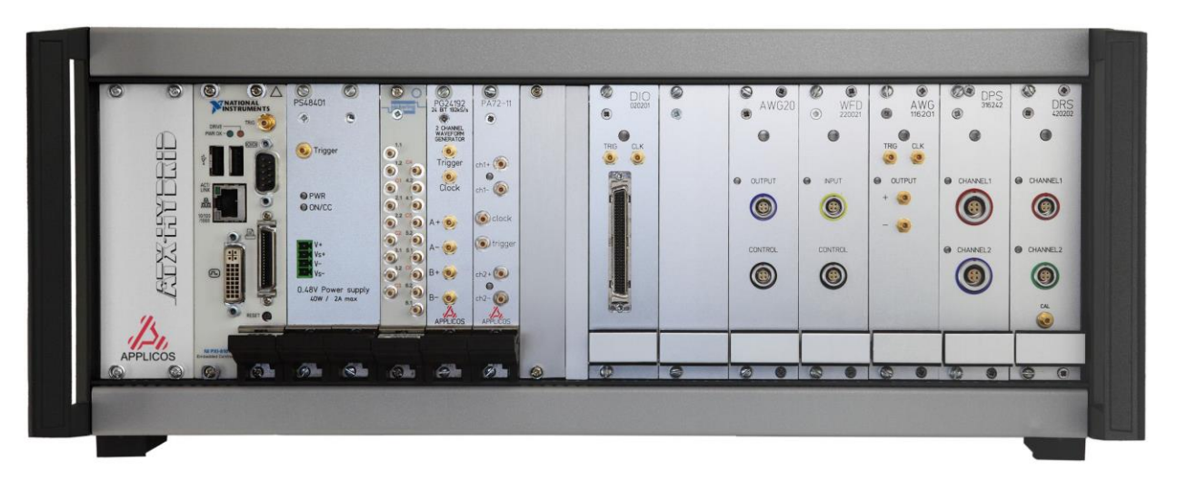
Standard ATX-slot configuration: 20-bit AWG, 20-bit WFD, Dual Reference Source, Dual Power Supply and the Digital-IO module.
Features
• Fully integrated data converter test solution
• Sample rates from DC up to 200/400MHz
• Seven ATX-format slots and six PXI slots
• Clock synchronization between ATX- and PXI
• Flexible and versatile digital IO
• Extended Analysis software included
• Static, Dynamic and Histogram testing
• Expandable with both PXI and ATX modules
Summary of modules specifications (for full specifications see our website):
AWG20 module
Resolution / Update rate 20-bit / 2Msps
Pattern memory depth 4M-words
Output ranges (Vpp, SE) 80mV to 10.24V in x2 steps
Filters / DC offset voltage 8 filters (max.) / -5V to + 5V
Absolute accuracy ±(40µV + 10ppm of range)
Non Linearity (INL) ±8ppm of range (4ppm typical)
THD / SNR -108dB / 92dB (@1kHz)
AWG22 module
Resolution / Update rate 22-bit / 2Msps
Pattern memory depth 4M-words
Output ranges (Vpp, SE) 80mV to 10.20V in x2 steps
Filters / DC offset voltage 8 filters (max.) / -5.10V to + 5.10V
Absolute accuracy ±(25µV +8ppm of range)
Non Linearity (INL) ±3ppm of range (1.5ppm typical)
THD / SNR -111dB / 97dB (@1kHz)
AWG16 module
Resolution / Update rate* 16-bit / 400Msps
Pattern memory depth 8M-words
Output ranges (Vpp, SE) 480mVpp to 5.12Vpp in 8 ranges
Filters / DC offset voltage 15- 30- 60MHz / -2.56V to +2.56V
Absolute accuracy ±(500μV+0.08% of range)
Non Linearity ±0.003% of range
THD / SNR -87dB / 70dB (@1MHz)
AWG18 module
Resolution / Update rate* 18-bit / 300Msps (600Msps, 1.2Gsps)
Pattern memory depth 8M-words
Output ranges (Vpp, SE) 580mVpp to 6.56Vpp in 8 ranges
Filters / DC offset voltage 6 filters / -2.56V to +2.56V
Absolute accuracy ±(300V+0.02% of range)
Non Linearity ±0.004% of range
THD / SNR -99dB / 73dB (@10MHz)
WFD20 module
Resolution / Sample rate 20-bit / 2Msps
Capture memory depth 4M-words
Input ranges (Vpp) 0.544V to 8.16V in 8 ranges
Filters / DC offset voltage 800kHz, 250kHz, 40kHz / -5V to + 5V
Absolute accuracy ±(40µV + 10ppm of range)
Non Linearity (INL) ±8ppm of range (3ppm typical)
THD / SNR -110dB / 93dB (@1kHz)
WFD16 module
Resolution / Sample rate 16-bit / 180Msps
Capture memory depth 8M-words
Input ranges (Vpp) 0.512V to 7.688V in 16 ranges
Filters / DC offset voltage 15- 30- 60MHz / equal to input range
Absolute accuracy ±(800μV+0.1% of range)
Non Linearity (INL) ±0.006% of range
THD / SNR -89dB / 70dB (@1MHz)
DC modules → Dual Ref. Source Dual Power Supply
Outputs/ res./ settl. 2ch. / 20-bit / 20ms 2ch. / 16-bit / 10ms
Output range/config. ±10V / 2 or 4-wire ±12V / 2 or 4 wire
Accuracy ±(25µV+10ppm.Vo) ±(4mV+0.2%.Vout)
Noise (DC- 100kHz) 5μVrms (typical) 18μVrms (typical)
Output current 10mA 200mA
Voltage readback 24-bit (DVM function) 16-bit (volt¤t)
V-out modulation n.a. 1mHz - 1kHz
DIO & DIOII module
Data In- Outputs 20/24-bit, parallel, byte-byte, serial
Capture & Stimuli memory 8Mword x 16 or 4Mword x 24 bits
Max. data&clock rate 50MHz LS mode / 200MHz HS mode
DIOII max. clock rate 600MHz on backplane / 1GHz front
Digital I/O levels 1.2V - 3.3/5V CMOS & LVDS
Clock jitter (DIOII) 190fs (typical@100MHz)
* Update rates >200MHz require DIOII or an external clock source